Mini Mill Brushless Spindle Drive
I burnt out the old motor on my milling machine and replacement motors are expensive. I decided to try a big brushless motor sold for use in rc airplanes. The thing I didn't think about was how expensive it would be to supply 30 volts/100 amp power to the spindle.
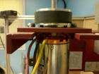
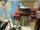
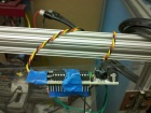
Here is the mount and pulley system I built when I first got the motor. The biggest issue with this setup are the plastic standoffs on the face of the motor. Also the motor is not built to handle the potentially large overhung load from the drive pulley. The first thing I did was replace original motor shaft with a tougher alloy (I forget what). On the rightmost picture you can see the microcontroller that generates the signal required for the brushless motor controller I'm using.
|
|
|
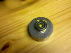
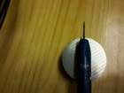
Here is the 2.5" x 1" aluminum disk that will be used to make a heatsink/bearing block. The new ball bearing is several times larger that the one built into the body of the motor.
|
|
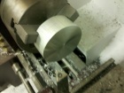
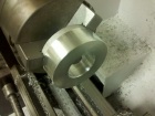
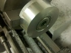
The disk is faced off before a recess is bored to seat the ball bearing. The corners have a .5mm chamfer; the bearing recess is an extra .5mm deep to compensate.
|
|
|
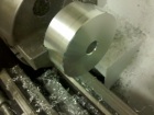
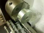
The disk is flipped and the back side is faced off and chamfered.
|
|
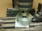
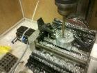
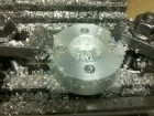
After the turning all the mounting holes are drilled in the cnc mill. The 4 holes that secure the disk to the front of the motor are also counterbored.
|
|
|
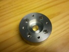
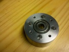
The finished bearing block with and without the bearing in place.
|
|
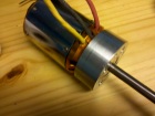
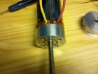
It fits onto the front of the motor as expected.
|
|
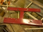
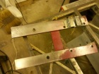
The old motor mounting bracket needed a few modifications because the motor is now flipped downward and I have always needed to add a decent place to hold the spindle locking pin.
|
|
|
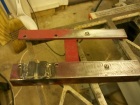
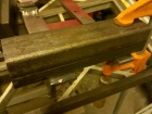
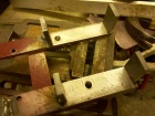
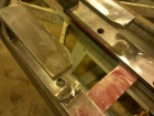
I welded on standoffs to allow the motor to be placed above the spindle away from milling chips and oil. I forgot to consider the path of the belt and had to rework some of the mounting bracket.
|
|
|
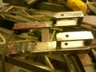
Now there is plenty of space for the drive belt to pass through.
|