First Batch of PCBs
My goal is to practice designing PCBs as well as make something useful. Here is a very simple board that drives a text lcd using an atmel atmega 328.
The boards
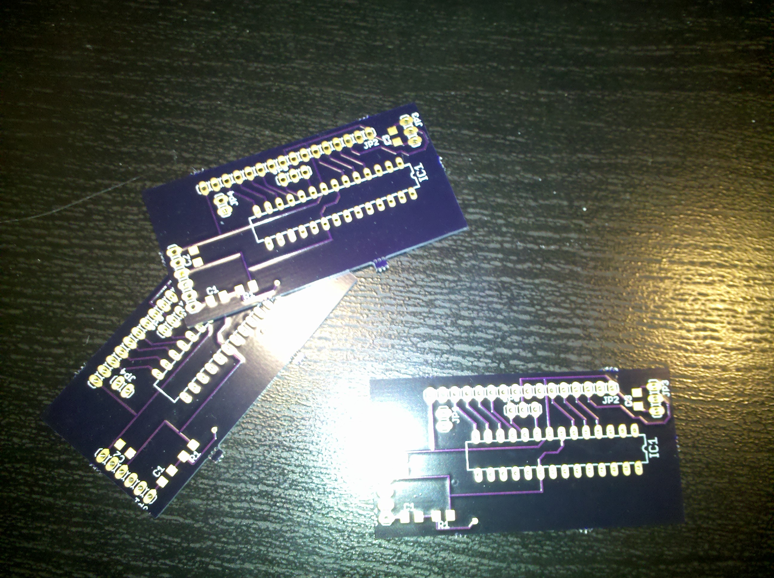
|
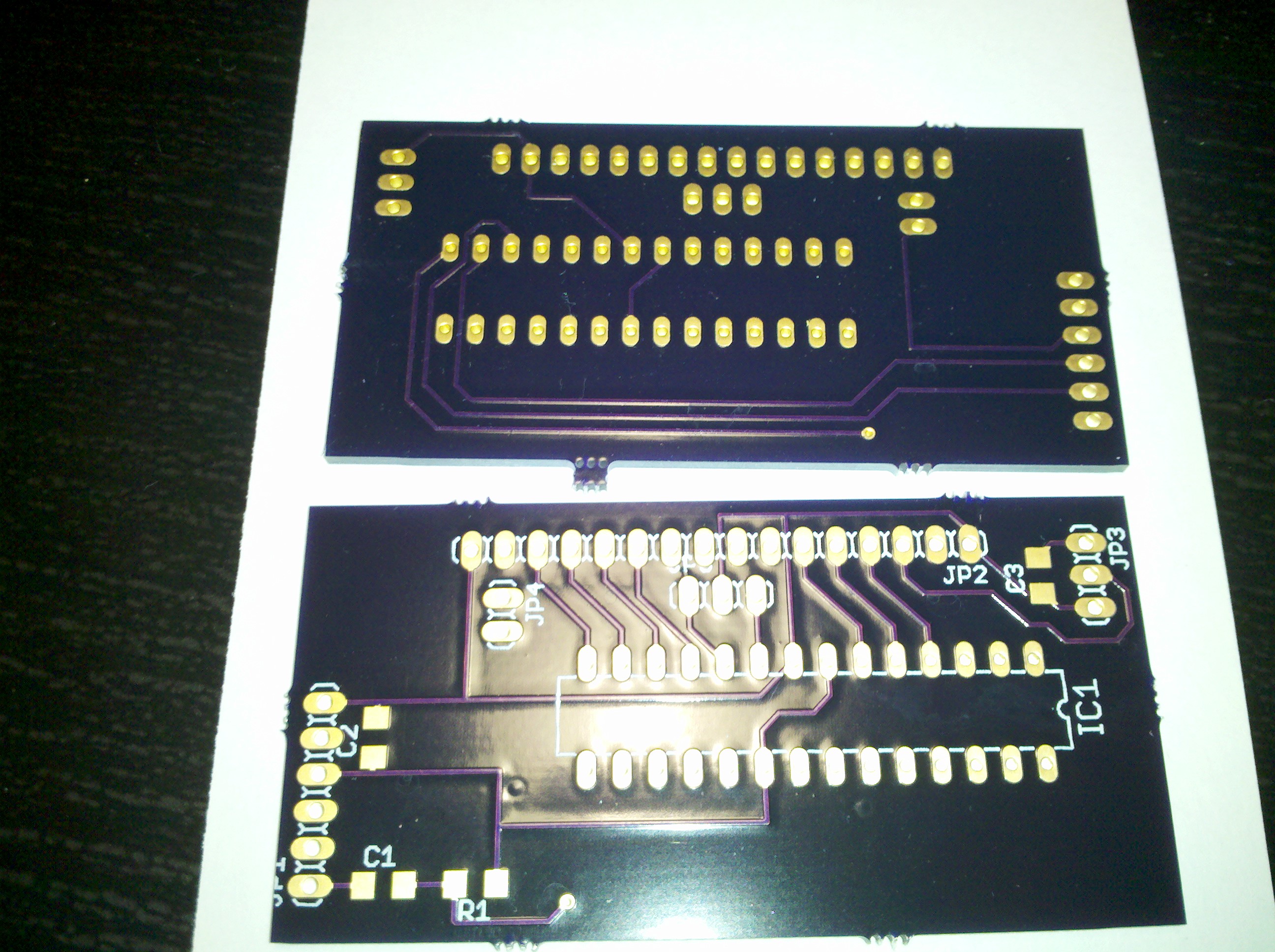
|
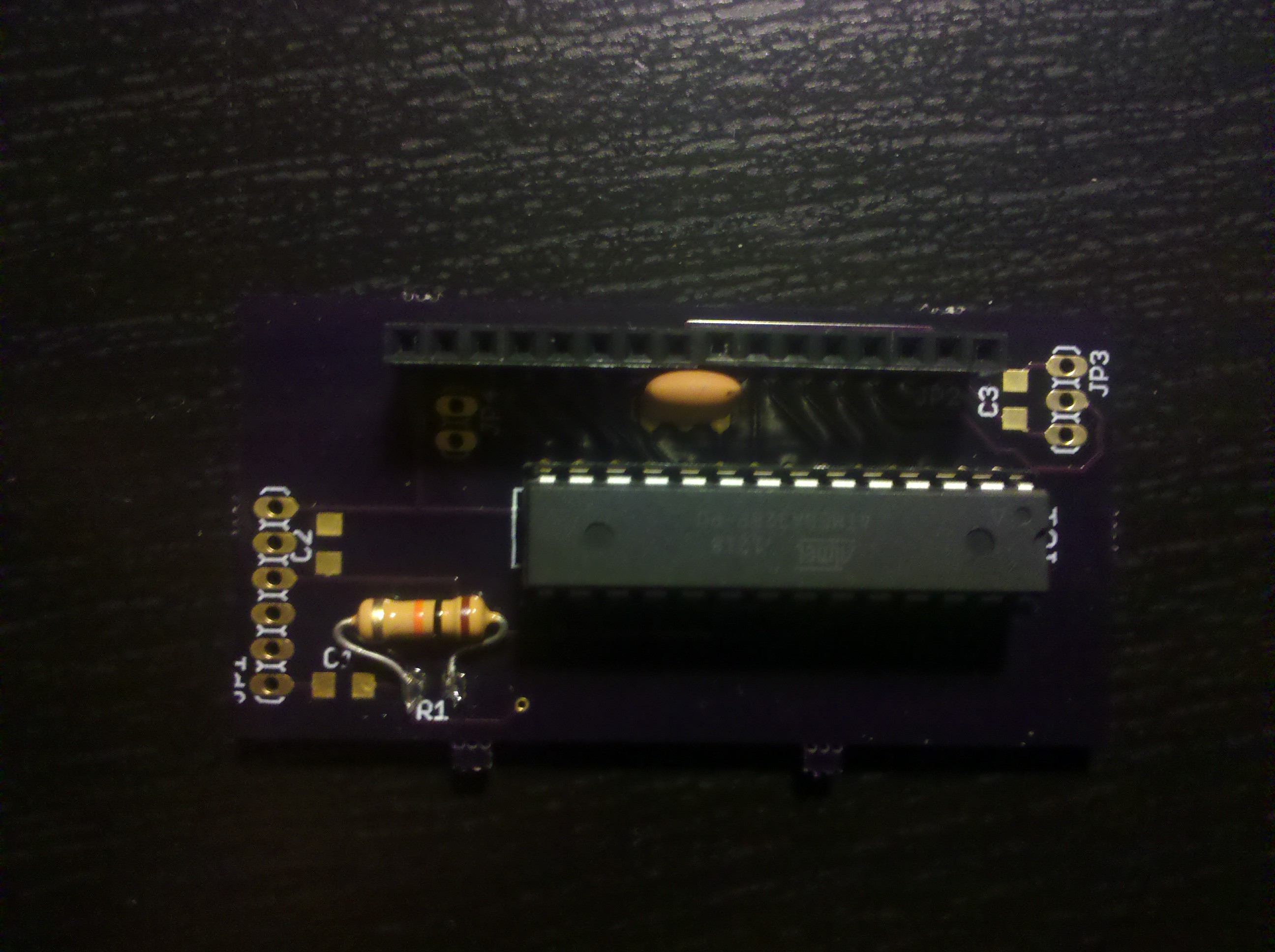
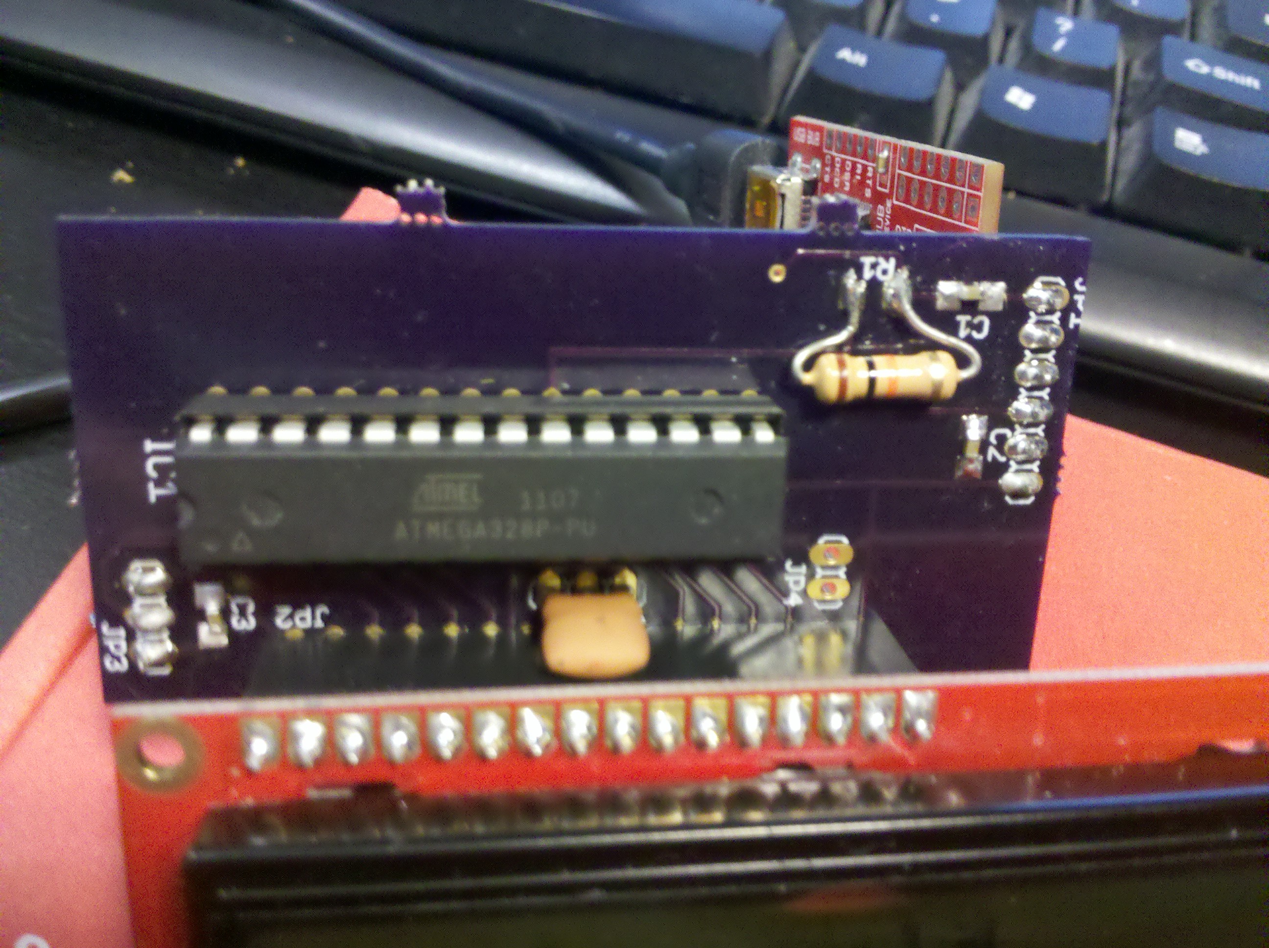
All there is to the board is the atmega, a 16 mhz resonator, a few decoupling capacitors, a potentiometer, and a resistor. I didn't have any smd components when I first started populating the board so I soldered a resistor on pads meant for a 1206 package; I decided to wait until I got some smd parts before hacking the rest of them on this way.
|
Here is the prototype on a breadboard.
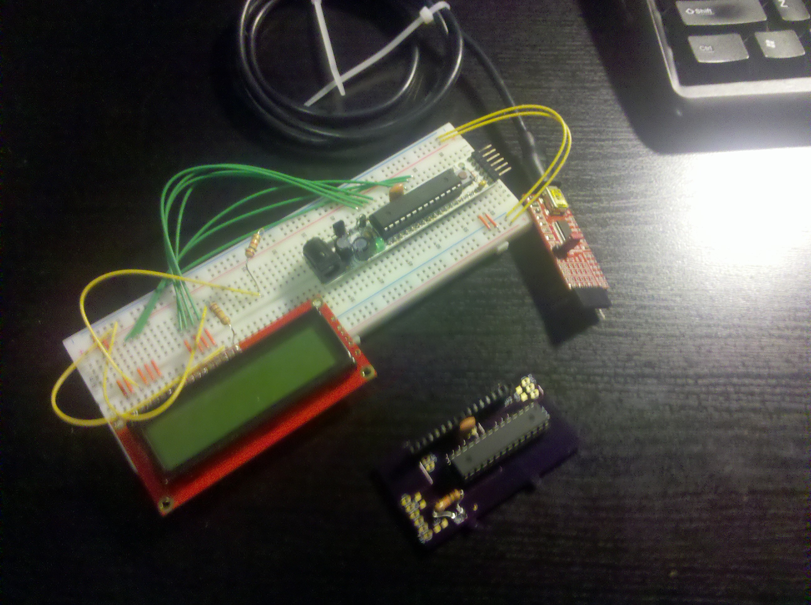
|
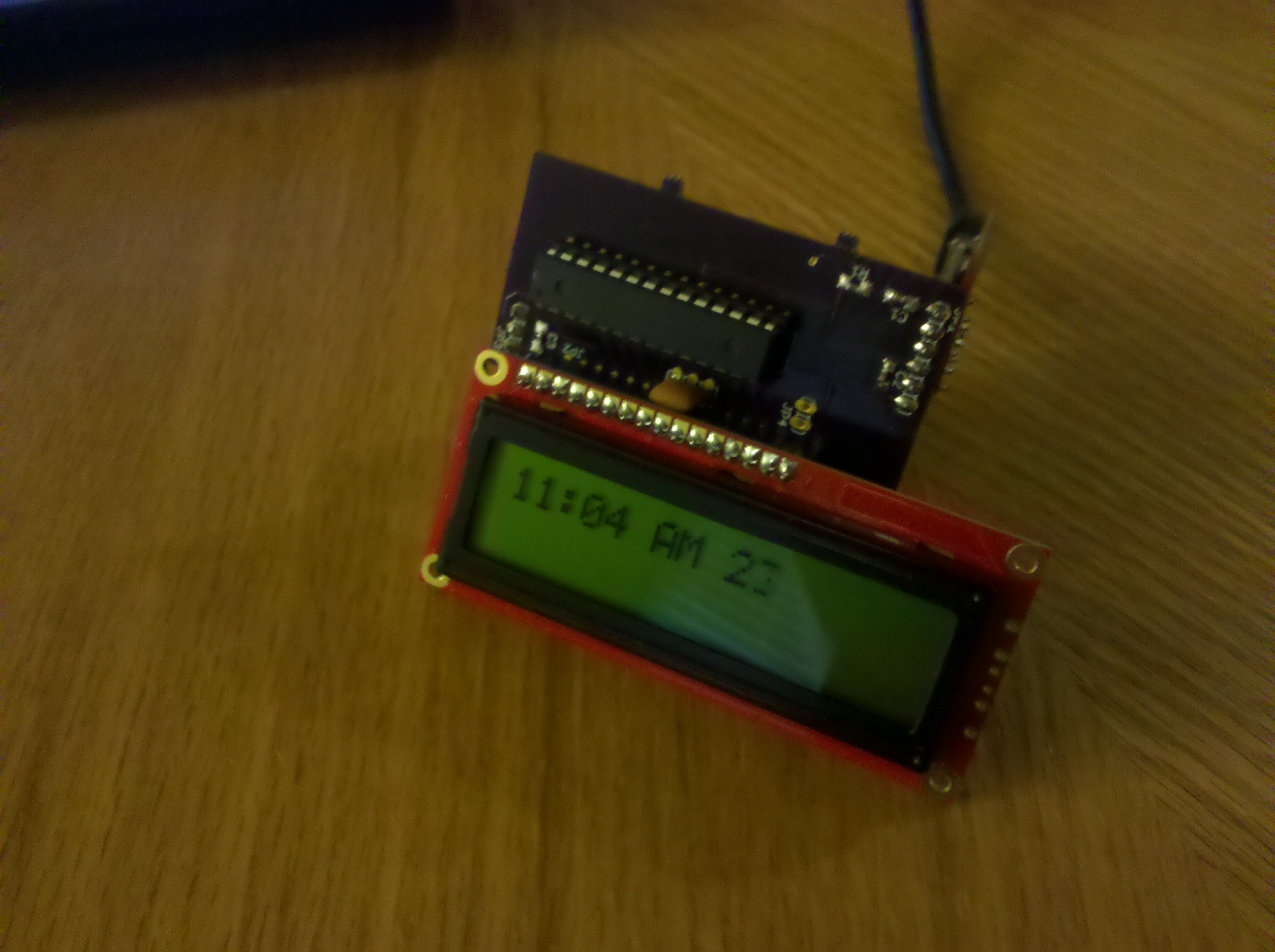
It works!

|
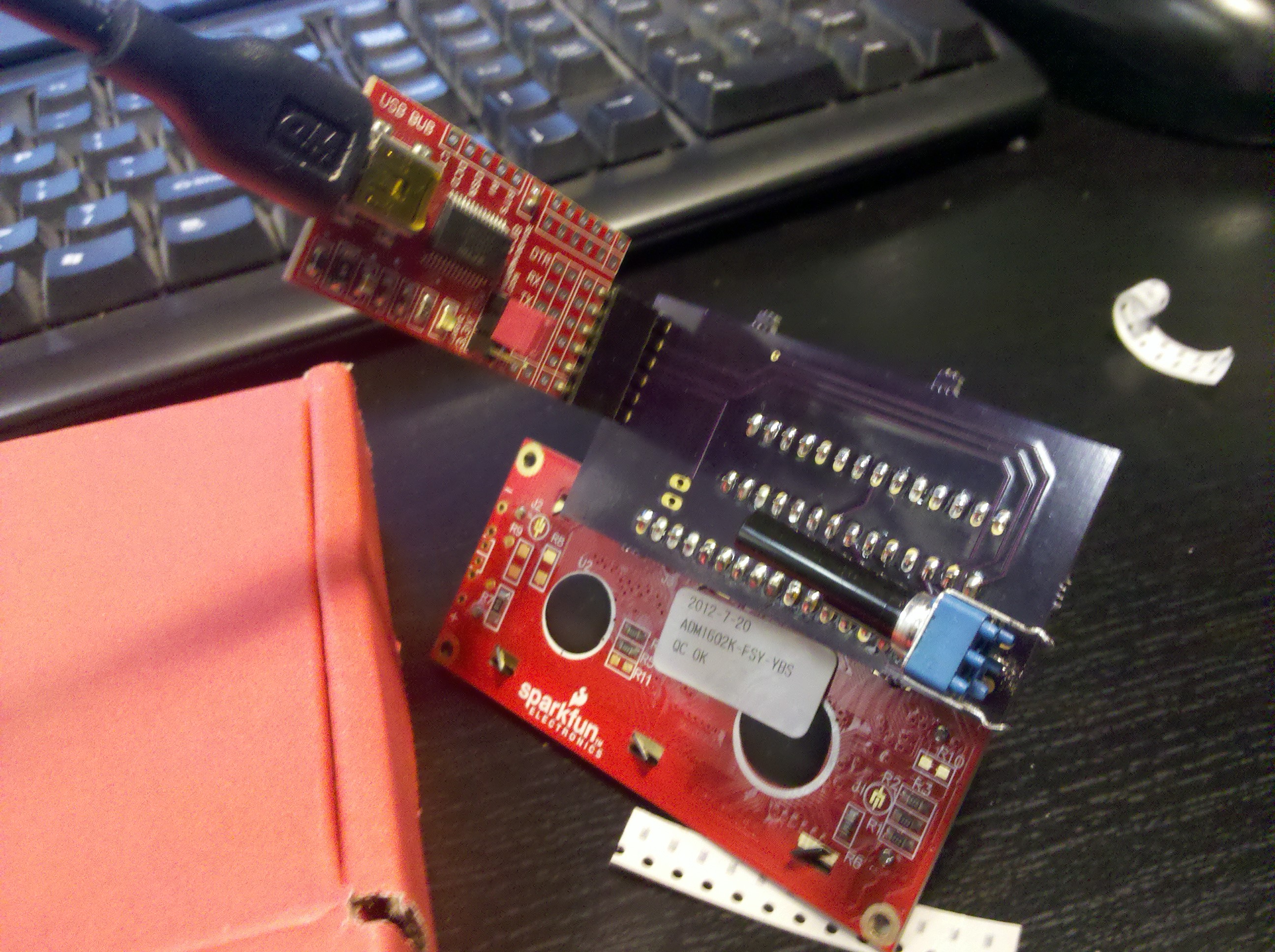
A few pictures of the assembled board, the through hole resistor has since been replaced.
|
|
I wrote some firmware to read incoming strings from the UART and write to the LCD. I have a C# program writing the time out over the serial port every few hundred milliseconds.
|
From here..
usb-serial adapter, better board layout